AWG
From HwB
(Difference between revisions)
(Completely rewritten from scratch) |
(Inch diameter added to graphs) |
||
| (2 intermediate revisions by one user not shown) | |||
| Line 59: | Line 59: | ||
|} | |} | ||
| − | ''Note: At 20°C ( | + | ''Note: At 20°C (68°F)'' |
== Diameter graph == | == Diameter graph == | ||
| Line 65: | Line 65: | ||
<gnuplot> | <gnuplot> | ||
set output 'AWG_diameter1.png' | set output 'AWG_diameter1.png' | ||
| − | set terminal png | + | set terminal png notransparent interlace size 800,400 enhanced |
set size 1.0,1.0 | set size 1.0,1.0 | ||
set grid x y | set grid x y | ||
| − | set ytics 1 | + | set yrange [0:12.7] |
| + | set y2range [0:0.5] | ||
| + | set ytics 0,1 | ||
| + | set y2tics 0,0.0625 | ||
set xtics ("0000" -3, "000" -2, "00" -1, "0" 0 0, "1" 1, "2" 2, "3" 3, "4" 4, "5" 5, "6" 6, "7" 7, "8" 8, "9" 9, "10" 10, "11" 11, "12" 12, "13" 13, "14" 14, "15" 15, "16" 16, "17" 17, "18" 18, "19" 19, "20" 20, "21" 21, "22" 22, "23" 23, "24" 24, "25" 25, "26" 26, "27" 27, "28" 28, "29" 29, "30" 30, "31" 31, "32" 32, "33" 33, "34" 34, "35" 35, "36" 36, "37" 37, "38" 38, "39" 39, "40" 40, "41" 41, "42" 42, "43" 43, "44" 44, "45" 45, "46" 46) | set xtics ("0000" -3, "000" -2, "00" -1, "0" 0 0, "1" 1, "2" 2, "3" 3, "4" 4, "5" 5, "6" 6, "7" 7, "8" 8, "9" 9, "10" 10, "11" 11, "12" 12, "13" 13, "14" 14, "15" 15, "16" 16, "17" 17, "18" 18, "19" 19, "20" 20, "21" 21, "22" 22, "23" 23, "24" 24, "25" 25, "26" 26, "27" 27, "28" 28, "29" 29, "30" 30, "31" 31, "32" 32, "33" 33, "34" 34, "35" 35, "36" 36, "37" 37, "38" 38, "39" 39, "40" 40, "41" 41, "42" 42, "43" 43, "44" 44, "45" 45, "46" 46) | ||
set xlabel "AWG" | set xlabel "AWG" | ||
set ylabel "Diameter (mm)" | set ylabel "Diameter (mm)" | ||
| − | plot [x=21:-3] 0.005*92**((36-x)/39)*25.4 notitle | + | set y2label "Diameter (inch)" |
| + | plot [x=21:-3] 0.005*92**((36-x)/39)*25.4 notitle,0.005*92**((36-x)/39) axis x1y2 notitle | ||
</gnuplot> | </gnuplot> | ||
=== AWG 46 - 22 === | === AWG 46 - 22 === | ||
<gnuplot> | <gnuplot> | ||
set output 'AWG_diameter2.png' | set output 'AWG_diameter2.png' | ||
| − | set terminal png | + | set terminal png notransparent interlace size 800,400 enhanced |
set size 1.0,1.0 | set size 1.0,1.0 | ||
set grid x y | set grid x y | ||
| + | set yrange [0:0.635] | ||
| + | set y2range [0:0.025] | ||
| + | set ytics 0,1 | ||
| + | set y2tics 0,0.0025 | ||
set ytics 0,0.1 | set ytics 0,0.1 | ||
set xtics ("0000" -3, "000" -2, "00" -1, "0" 0 0, "1" 1, "2" 2, "3" 3, "4" 4, "5" 5, "6" 6, "7" 7, "8" 8, "9" 9, "10" 10, "11" 11, "12" 12, "13" 13, "14" 14, "15" 15, "16" 16, "17" 17, "18" 18, "19" 19, "20" 20, "21" 21, "22" 22, "23" 23, "24" 24, "25" 25, "26" 26, "27" 27, "28" 28, "29" 29, "30" 30, "31" 31, "32" 32, "33" 33, "34" 34, "35" 35, "36" 36, "37" 37, "38" 38, "39" 39, "40" 40, "41" 41, "42" 42, "43" 43, "44" 44, "45" 45, "46" 46) | set xtics ("0000" -3, "000" -2, "00" -1, "0" 0 0, "1" 1, "2" 2, "3" 3, "4" 4, "5" 5, "6" 6, "7" 7, "8" 8, "9" 9, "10" 10, "11" 11, "12" 12, "13" 13, "14" 14, "15" 15, "16" 16, "17" 17, "18" 18, "19" 19, "20" 20, "21" 21, "22" 22, "23" 23, "24" 24, "25" 25, "26" 26, "27" 27, "28" 28, "29" 29, "30" 30, "31" 31, "32" 32, "33" 33, "34" 34, "35" 35, "36" 36, "37" 37, "38" 38, "39" 39, "40" 40, "41" 41, "42" 42, "43" 43, "44" 44, "45" 45, "46" 46) | ||
set xlabel "AWG" | set xlabel "AWG" | ||
set ylabel "Diameter (mm)" | set ylabel "Diameter (mm)" | ||
| − | plot [x=46:22] 0.005*92**((36-x)/39)*25.4 notitle | + | set y2label "Diameter (inch)" |
| + | plot [x=46:22] 0.005*92**((36-x)/39)*25.4 notitle,0.005*92**((36-x)/39) axis x1y2 notitle | ||
</gnuplot> | </gnuplot> | ||
| Line 91: | Line 100: | ||
<gnuplot> | <gnuplot> | ||
set output 'AWG_area1.png' | set output 'AWG_area1.png' | ||
| − | set terminal png | + | set terminal png notransparent interlace size 800,400 enhanced |
set size 1.0,1.0 | set size 1.0,1.0 | ||
set grid x y | set grid x y | ||
| Line 103: | Line 112: | ||
<gnuplot> | <gnuplot> | ||
set output 'AWG_area2.png' | set output 'AWG_area2.png' | ||
| − | set terminal png | + | set terminal png notransparent interlace size 800,400 enhanced |
set size 1.0,1.0 | set size 1.0,1.0 | ||
set grid x y | set grid x y | ||
| Line 115: | Line 124: | ||
<gnuplot> | <gnuplot> | ||
set output 'AWG_area3.png' | set output 'AWG_area3.png' | ||
| − | set terminal png | + | set terminal png notransparent interlace size 800,400 enhanced |
set size 1.0,1.0 | set size 1.0,1.0 | ||
set grid x y | set grid x y | ||
| Line 129: | Line 138: | ||
<gnuplot> | <gnuplot> | ||
set output 'AWG_resistance1.png' | set output 'AWG_resistance1.png' | ||
| − | set terminal png | + | set terminal png notransparent interlace size 800,400 enhanced |
set size 1.0,1.0 | set size 1.0,1.0 | ||
set grid x y | set grid x y | ||
| Line 141: | Line 150: | ||
<gnuplot> | <gnuplot> | ||
set output 'AWG_resistance2.png' | set output 'AWG_resistance2.png' | ||
| − | set terminal png | + | set terminal png notransparent interlace size 800,400 enhanced |
set size 1.0,1.0 | set size 1.0,1.0 | ||
set grid x y | set grid x y | ||
| Line 153: | Line 162: | ||
<gnuplot> | <gnuplot> | ||
set output 'AWG_resistance3.png' | set output 'AWG_resistance3.png' | ||
| − | set terminal png | + | set terminal png notransparent interlace size 800,400 enhanced |
set size 1.0,1.0 | set size 1.0,1.0 | ||
set grid x y | set grid x y | ||
Latest revision as of 16:43, 25 January 2007
AWG=American Wire Gauge standard
Contents |
Table
| Gauge | Diam | Area | R | I at 3A/mm2 |
|---|---|---|---|---|
| AWG | mm | mm2 | Ω/km | A |
| 46 | 0.0398 | 0.00125 | 13800 | 0.00374 |
| 45 | 0.0447 | 0.00157 | 11000 | 0.00471 |
| 44 | 0.0502 | 0.00198 | 8700 | 0.00595 |
| 43 | 0.0564 | 0.0025 | 6900 | 0.0075 |
| 42 | 0.0633 | 0.00315 | 5470 | 0.00945 |
| 41 | 0.0711 | 0.00397 | 4340 | 0.0119 |
| 40 | 0.0799 | 0.00501 | 3440 | 0.015 |
| 39 | 0.0897 | 0.00632 | 2730 | 0.019 |
| 38 | 0.101 | 0.00797 | 2160 | 0.0239 |
| 37 | 0.113 | 0.01 | 1720 | 0.0301 |
| 36 | 0.127 | 0.0127 | 1360 | 0.038 |
| 35 | 0.143 | 0.016 | 1080 | 0.0479 |
| 34 | 0.16 | 0.0201 | 856 | 0.0604 |
| 33 | 0.18 | 0.0254 | 679 | 0.0762 |
| 32 | 0.202 | 0.032 | 538 | 0.0961 |
| 31 | 0.227 | 0.0404 | 427 | 0.121 |
| 30 | 0.255 | 0.0509 | 339 | 0.153 |
| 29 | 0.286 | 0.0642 | 268 | 0.193 |
| 28 | 0.321 | 0.081 | 213 | 0.243 |
| 27 | 0.361 | 0.102 | 169 | 0.306 |
| 26 | 0.405 | 0.129 | 134 | 0.386 |
| 25 | 0.455 | 0.162 | 106 | 0.487 |
| 24 | 0.511 | 0.205 | 84.2 | 0.614 |
| 23 | 0.573 | 0.258 | 66.8 | 0.774 |
| 22 | 0.644 | 0.326 | 53 | 0.977 |
| 21 | 0.723 | 0.41 | 42 | 1.23 |
| 20 | 0.812 | 0.518 | 33.3 | 1.55 |
| 19 | 0.912 | 0.653 | 26.4 | 1.96 |
| 18 | 1.02 | 0.823 | 20.9 | 2.47 |
| 17 | 1.15 | 1.04 | 16.6 | 3.11 |
| 16 | 1.29 | 1.31 | 13.2 | 3.93 |
| 15 | 1.45 | 1.65 | 10.4 | 4.95 |
| 14 | 1.63 | 2.08 | 8.29 | 6.24 |
| 13 | 1.83 | 2.62 | 6.57 | 7.87 |
| 12 | 2.05 | 3.31 | 5.21 | 9.93 |
| 11 | 2.3 | 4.17 | 4.13 | 12.5 |
| 10 | 2.59 | 5.26 | 3.28 | 15.8 |
| 9 | 2.91 | 6.63 | 2.6 | 19.9 |
| 8 | 3.26 | 8.37 | 2.06 | 25.1 |
| 7 | 3.66 | 10.5 | 1.63 | 31.6 |
| 6 | 4.12 | 13.3 | 1.3 | 39.9 |
| 5 | 4.62 | 16.8 | 1.03 | 50.3 |
| 4 | 5.19 | 21.2 | 0.815 | 63.5 |
| 3 | 5.83 | 26.7 | 0.646 | 80 |
| 2 | 6.54 | 33.6 | 0.513 | 101 |
| 1 | 7.35 | 42.4 | 0.407 | 127 |
| 0 | 8.25 | 53.5 | 0.322 | 160 |
| 00 | 9.27 | 67.4 | 0.256 | 202 |
| 000 | 10.4 | 85 | 0.203 | 255 |
| 0000 | 11.7 | 107 | 0.161 | 322 |
Note: At 20°C (68°F)
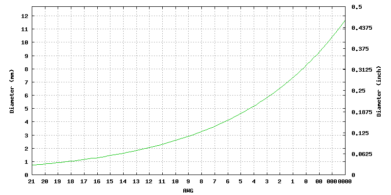
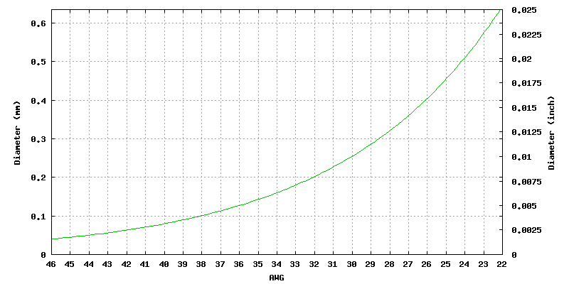
Diameter graph
AWG 21 - 0000
AWG 46 - 22
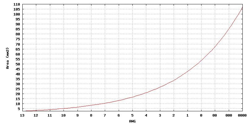
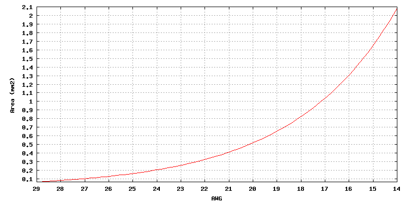
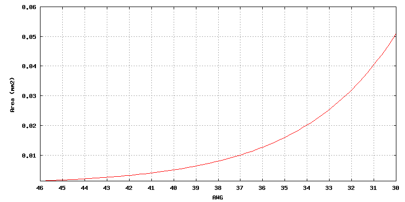
Area graph
AWG 13 - 0000
AWG 29 - 14
AWG 46 - 30
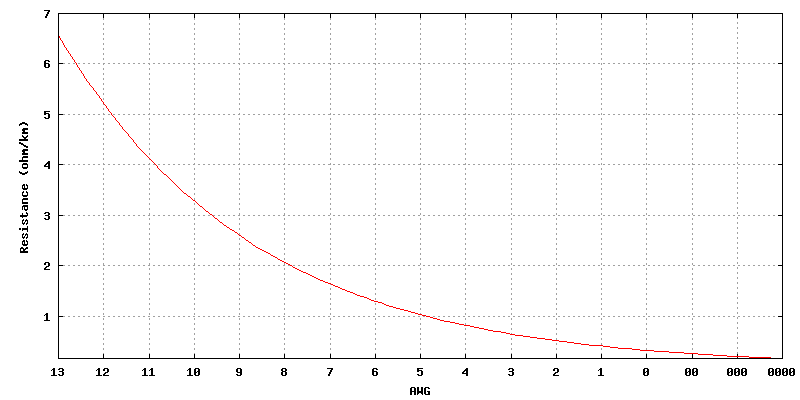
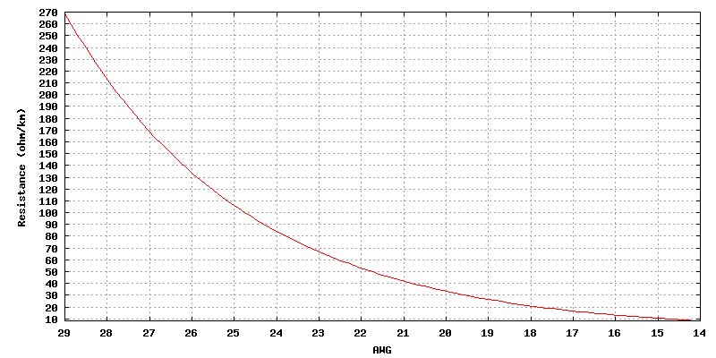
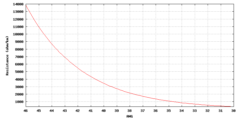
Resistance graph
AWG 13 - 0000
AWG 29 - 14
AWG 46 - 30
Contributions
Source
- Formulas from Standard Handbook for Electrical Engineers (14th Ed, 2000) ISBN 0-07-022005-0