Serial (PC 25)
From HwB
(Difference between revisions)
m (added See also) |
|||
| (One intermediate revision by one user not shown) | |||
| Line 22: | Line 22: | ||
| 7 || GND || - || System Ground | | 7 || GND || - || System Ground | ||
|- | |- | ||
| − | | 8 || CD || {{arrowl}} || Carrier Detect | + | | 8 || (D)CD || {{arrowl}} || (Data) Carrier Detect |
|- | |- | ||
| 9 || n/c || - || | | 9 || n/c || - || | ||
| Line 66: | Line 66: | ||
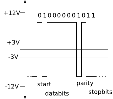
[[Image:RS232_Diagram.svg]] | [[Image:RS232_Diagram.svg]] | ||
| + | |||
| + | == See also == | ||
| + | * [[RS232]] | ||
== Contributions == | == Contributions == | ||
Latest revision as of 13:17, 16 July 2019
Contents |
Pinout
25 PIN D-SUB MALE at the computer.
| Pin | Name | Dir | Description |
|---|---|---|---|
| 1 | SHIELD | - | Shield Ground |
| 2 | TXD | |
Transmit Data |
| 3 | RXD | |
Receive Data |
| 4 | RTS | |
Request to Send |
| 5 | CTS | |
Clear to Send |
| 6 | DSR | |
Data Set Ready |
| 7 | GND | - | System Ground |
| 8 | (D)CD | |
(Data) Carrier Detect |
| 9 | n/c | - | |
| 10 | n/c | - | |
| 11 | n/c | - | |
| 12 | n/c | - | |
| 13 | n/c | - | |
| 14 | n/c | - | |
| 15 | n/c | - | |
| 16 | n/c | - | |
| 17 | n/c | - | |
| 18 | n/c | - | |
| 19 | n/c | - | |
| 20 | DTR | |
Data Terminal Ready |
| 21 | n/c | - | |
| 22 | RI | |
Ring Indicator |
| 23 | n/c | - | |
| 24 | n/c | - | |
| 25 | n/c | - |
Notes:
- Direction is DTE (Computer) relative DCE (Modem).
- Do not connect SHIELD(1) to GND(7).
Technical
See also
Contributions
Sources
- Amiga 4000 User's Guide from Commodore

