From HwB
| Line 10: | Line 10: | ||
But, as with any advanced hardware, there's a few snags. In this case, it would be that the 24 ports are not working simultaneous, but rather switched between in set's of 3 (Or really set's of 4. -It get's more complicated later) 8- bit channels if you like. These bit's are bi-directional, which in short means that they operate at both directions. -In and out, but one at the time, depending of what mode the circuit is set to. | But, as with any advanced hardware, there's a few snags. In this case, it would be that the 24 ports are not working simultaneous, but rather switched between in set's of 3 (Or really set's of 4. -It get's more complicated later) 8- bit channels if you like. These bit's are bi-directional, which in short means that they operate at both directions. -In and out, but one at the time, depending of what mode the circuit is set to. | ||
| − | Another snag is that these circuits are hard to come by. According to our (Sweden) biggest importer of electronics, | + | Another snag is that these circuits are hard to come by. According to our (Sweden) biggest importer of electronics, ELFA, this circuit is obsolete, which is a damn shame, given it's potential and usefulness!!! |
If you know of any other circuit that replaces this, and has a DIL-capsul (I'm not too fond of PLCC and simmilar! It's painstaking to handle!), please send me a link at [email protected] | If you know of any other circuit that replaces this, and has a DIL-capsul (I'm not too fond of PLCC and simmilar! It's painstaking to handle!), please send me a link at [email protected] | ||
Latest revision as of 01:51, 26 November 2007
Ok.. I'm new to this new HwB-site, and it screams Wiki all over the place... I'm currently quite tired, but I'm damned if I can't insert my (Actually, others...) "work" someplace. So, it might just as well be here, for now.
Anywhoo, I thought I'd publish something that's not easy to come by nowadays... Took some serious Googeling to find it in the first place. Well, down to business:
It's a 24- port ISA I/O- card. Not exactly the hottest thing on the market. But, a damn nifty thingie. This one card allows you to directly (<-Take this comment with a pinch of salt) access your ISA- bus and forego the annoying I/O's of the LPTx.
But, as with any advanced hardware, there's a few snags. In this case, it would be that the 24 ports are not working simultaneous, but rather switched between in set's of 3 (Or really set's of 4. -It get's more complicated later) 8- bit channels if you like. These bit's are bi-directional, which in short means that they operate at both directions. -In and out, but one at the time, depending of what mode the circuit is set to.
Another snag is that these circuits are hard to come by. According to our (Sweden) biggest importer of electronics, ELFA, this circuit is obsolete, which is a damn shame, given it's potential and usefulness!!!
If you know of any other circuit that replaces this, and has a DIL-capsul (I'm not too fond of PLCC and simmilar! It's painstaking to handle!), please send me a link at [email protected]
The circuit is named 8255A and comes in a few diffrent flavors. Personally I've never been dealing with any diffrent of these chips, but it's always been the fact that I've either been too occupied with computers (It's a curse, because if you know the real basic's, you'll always end up helping others, all the time), or otherwise occupied. Of course, I've been running on fumes past 7-8 years when it comes to electronics, and a few months ago I really gave myself a swift kick in the head, and started to read up on the subject again.
Well, let's not have this entire section about me, so, Back2Business@YourEnd!
This is what it could look like, should you choose to build a similar:

Thanks to Intel Corporation for permission to reprint from their Component Data Catalog, Copyright 1978.
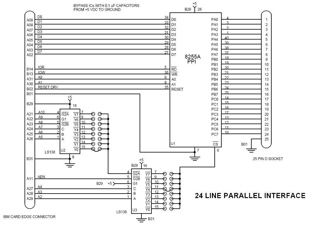
24 LINE PARALLEL INTERFACE
The Wenzel Associates Model 20-24 Parallel Interface is a general purpose, programmable I/O board for use with the IBM Personal Computer. Its 24 I/O lines are available on a 25 pin D connector and may be programmed as inputs, outputs, or both. These lines are TTL compatible, and have the added feature that most lines can source I ma at 1.5 volts to directly drive I)arlington type drivers and high-voltage displays.
The parallel interface requires 4 bytes of addressing and may be jumpered to recognize one of 64 address groups beginning with &H200, ending with &H2FC.
The Model 20-24 Interface is controlled by an 8255A Programmable Peripheral Interface I.C. that may be used in three modes of operation.
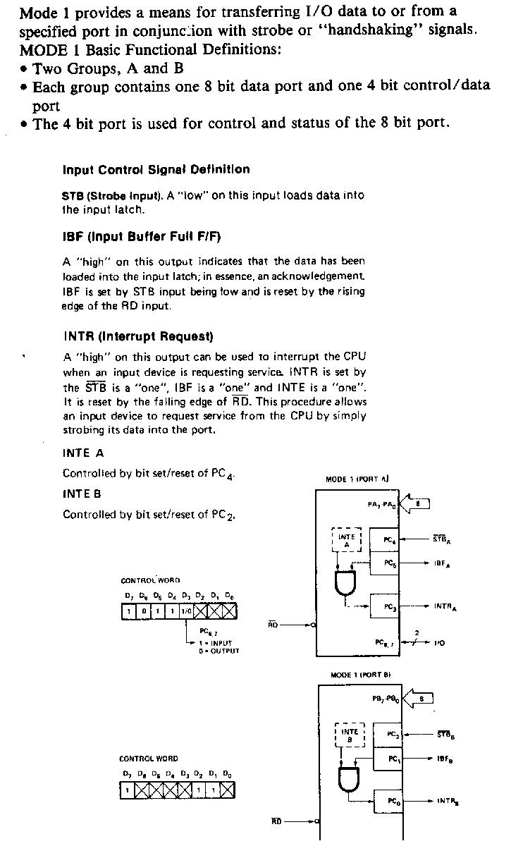
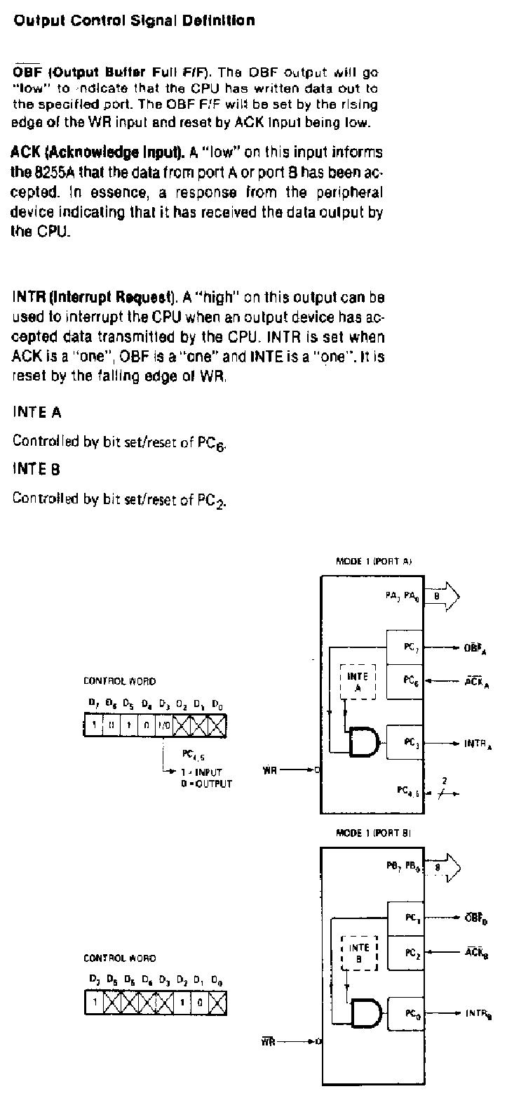
In the basic mode, MODE 0, the 24 I/O lines are divided into two eight line groups and two four line groups. Each group may be configured in software as all inputs or all outputs by writing a configuration command to the control register. MODE 1 separates the 24 lines into two eight line groups, with the eight remaining lines providing control or "handshaking" functions for each group. Data direction is set through the control register.
The third mode, MODE 2, creates a true bidirectional bus on eight of the I/O Lines. Five additional lines provide status and control information for the bus. In all modes, data may be transferred to and from these I/O lines with the BASIC "OUT" and "INP" commands. Machine language programmers may use 8088 port commands. The Model 20-24 Parallel Interface may be used to interface almost any peripheral equipment to the IBM personal computer through software control, without the need for additional external logic circuitry.
Operational Description
A programming model of the 20-24 parallel interface contains three ports and a control register. Lines A, and A, on the internal bus, in conjunction with input and output commands, control selection of one of these registers. Please note that the control word register can ONLY be written into. No read operation of the control word is allowed.
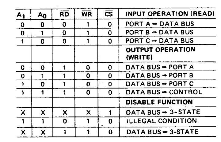

The addressing jumpers are set at the factory such that &H210 accesses PORT A &H211 accesses PORT B &H212 accesses PORT C &H213 accesses the CONTROL register Other address groups may be selected by replacing the addressing jumpers.


There are three basic modes of operation that can be selected by the system software:
Mode 0 - Basic Input/Output
Mode l - Strobed Input/Output Mode 2 - Bi-Directional Bus
When the IBM computer is powered up, or a system reset occurs, all ports will be set to input mode. The modes for Port A and Port B can be separately defined, while Port C is divided into two portions. All of the output registers, including the status flip-flops, will be reset whenever the mode is changed. Modes may be combined so that their functional definition can be tailored to almost any I/O structure. For instance, Group B can be programmed in Mode O to monitor simple switch closings or display computational results, Group A could be programmed in Mode 1 to monitor a keyboard or tape reader on an interrupt-driven basis.


Single Bit Set/Reset Feature Any of the eight bits of Port C can be set or reset using a single OUTPUT instruction. When Port C is being used as status/control for Port A or B these bits can be set or reset by using the Bit Set/Reset operation just as if they were data output ports.
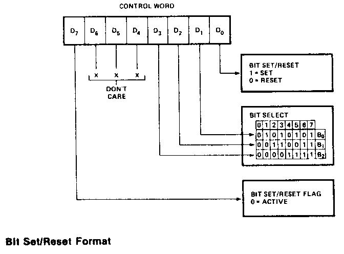

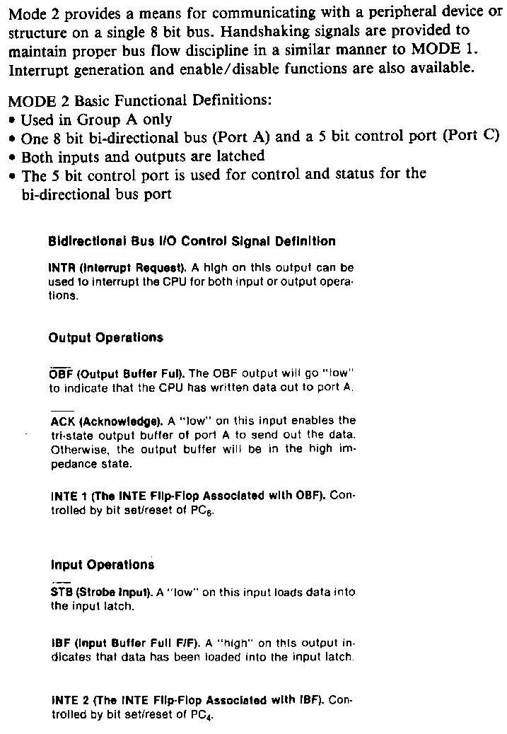
Interrupt Control Functions When the 8255A is programmed to operate in Mode 1 or Mode 2, control signals are provided that can be used as interrupt request inputs to the CPU. The interrupt request signals, generated from Port C can be inhibited or enabled by setting or resetting the associated INTE flip-flop using the bit set/reset function of Port C. Bit set enables interrupt and Bit reset disables the interrupt.
Operating Modes
Mode 0 provides simple input and output operations for each of the three ports. Data is simply written to or read from a specified port. MODE 0 Basic Functional Definitions: · Two 8 bit ports and two 4 bit ports · Any port can be input or output · Inputs are not latched · 16 different I/O configurations are possible
File:8255A-ModesDiagram-2.JPG


And now, for the schematic and the fun and interresting part:

When all is built and done, this little goodie may help you test the I/O-ports:


- Note: Sorry about the crap-ola- quality on the pictures, but I copied & pasted them from an PDF- file, all done with Acrobat Reader & MS Paint (MS Pain?).
I didn't feel like doin a heavy work just for the simple text. but if you like you can dl it here->[1]