ISDN S0-Bus
From HwB
This cable is used to connect ISDN devices together via an S0-Bus.
Pinout
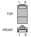
RJ45 MALE CONNECTOR to terminal endpoint (TE).
| Name | Pin | Cable Color | Pin | Name | ||
|---|---|---|---|---|---|---|
| 1 | 1 | |||||
| 2 | 2 | |||||
| 1a | 3 | Orange | 3 | TX+ | ||
| 2a | 4 | Blue | 4 | RX+ | ||
| 2b | 5 | White/Blue | 5 | RX- | ||
| 1b | 6 | White/Orange | 6 | TX- | ||
| 7 | 7 | |||||
| 8 | 8 |
RJ45 MALE CONNECTOR to network terminator (NT).
| Name | Pin | Cable Color | Pin | Name | ||
|---|---|---|---|---|---|---|
| 1 | 1 | |||||
| 2 | 2 | |||||
| 2a | 3 | Orange | 3 | RX+ | ||
| 1a | 4 | Blue | 4 | TX+ | ||
| 1b | 5 | White/Blue | 5 | TX- | ||
| 2b | 6 | White/Orange | 6 | RX- | ||
| 7 | 7 | |||||
| 8 | 8 |
Note: It's important that each pair is kept as a pair. 1a & 1b must be in the pair, and 2a & 2b must be together in another pair. (Just as the tables above show).
Just for your information, this is how the pairs are named:
| Pair | Pins | Common color |
|---|---|---|
| 1 | 4 & 5 | Blue |
| 2 | 1 & 2 | N.A. |
| 3 | 3 & 6 | Orange |
| 4 | 7 & 8 | N.A. |
The + side of each pair is called the "tip" and the - side is called the "ring", a reference to old telephone connectors.
